1. Overview
| This series is a linear pneumatic diaphragm actuator with multi-spring structure, light weight, small size, large output driving force and high performance. Its working principle is: The air pressure converted from the electric or pneumatic signal of the regulating instrument by the positioner is input into the diaphragm chamber, acting on the diaphragm to generate thrust, which causes the output shaft to move, and at the same time compresses the spring until it matches the reaction force of the spring. Balance so that the output shaft reaches the predetermined position. Position control can also be achieved by direct action of the air signal on the diaphragm. This series of actuators are divided into two types, positive acting (957) and counteracting (967). The design of the actuator enables the control valve to be reliably switched or regulated. See the figure on the right for the installation example of pneumatic actuator. | 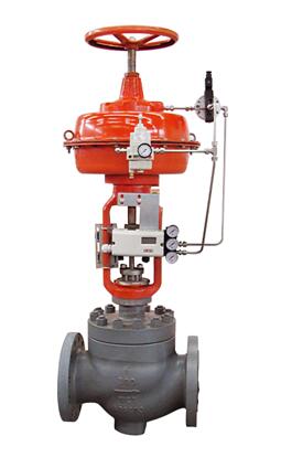 |
| Installation example |
2. Standard specifications
Series | 957、967 | |
Form | Multi-spring structure | |
Specification | 20、30、34、40、45、50、70 | |
Action | 1. Positive action 2. Reverse action | |
Maximum output thrust | See table 1 | |
Stroke | See table 2 | |
Supply pressure | 320Kpa | |
Spring range | Positive effect:20~100Kpa、40~200Kpa | |
Ambient temperature | Standard type: -40℃~82℃ Special type (optional): -18℃~149℃, -54℃~149℃ | |
Material of main parts | Standard | Membrane housing: steel Membrane: nitrile rubber Membrane plate: steel, O-ring: Nitrile rubber Stroke indicator: stainless steel Pointer: stainless steel, Actuator spring: steel Actuator guide rod: steel surface galvanized, Wafer block: galvanized steel surface Bracket: cast iron Hand wheel: nodular cast iron |
Special type | Film: Fluorine rubber (-18℃~149℃), silicone synthetic rubber (-54℃~149℃), O-ring: silicone synthetic rubber Actuator guide rod: stainless steel, Connecting bolt: stainless steel | |
Painting color | Orange | |
Attachment | Positioners, air filter pressure reducers, limit switches, solenoid valves, retaining valves, amplifiers, etc. | |
Optional equipment | Manual operating mechanism, special air piping and special air joints, high temperature environment, low temperature environment, salt corrosion type, designated coating color, etc. | |
Figure 1 Structure
Figure 1-1 Positive action (air-closed)
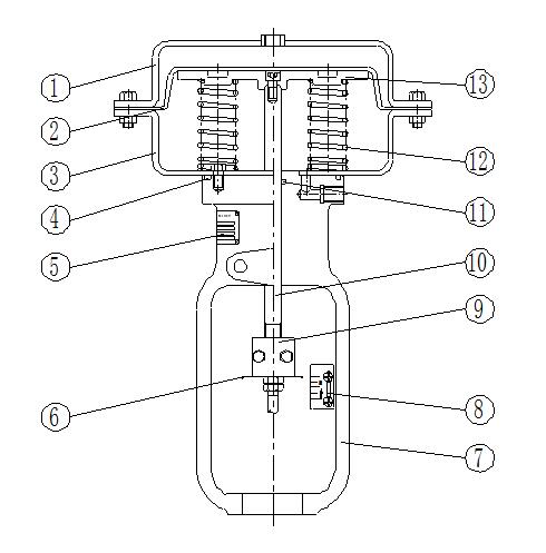
Figure 1-2 Reaction (air-to-open type)

Three, other configurations can be provided
Top/side mounting handwheel
In order to meet the manual operation in emergency situations, the 957 and 967 pneumatic diaphragm actuators can be equipped with a top-mounted or side-mounted handwheel assembly.
The top-mounted handwheel on the 957/967 actuator can be used to set the travel limit in the upward direction. The handwheel of 957 type actuator rotates clockwise to make the actuator push rod move downward to compress the spring; when the handwheel rotates counterclockwise, the action of the spring pushes the push rod back. For the Type 967 actuator, counterclockwise rotation will move the push rod upward; when clockwise rotation, the action of the spring will push the push rod downward.
The side-mounted handwheel on the 957/967 type actuator locates the handwheel on one side of the bracket. Through the worm gear drive, the handwheel drive can also be used as a stroke limiter.
Four, model preparation instructions

Example 1: Model: 957-30-S
Means: positive acting actuator, 30 actuator, with top-mounted handwheel, spring pressure range 20~100Kpa
Example 2: Model: 967L-40-C-T
Means: lengthened reaction type actuator, 40 actuator, with side-mounted handwheel, spring pressure range 120~240Kpa
Table 1 Maximum output thrust
Actuator series | Pre-compression force (Kpa) | Spring range (Kpa) | Air pressure (Kpa) | Maximum output thrust (Kgf) | ||||||
Actuator specifications | ||||||||||
20 | 30 | 34 | 40 | 45 | 50 | 70 | ||||
957 | 20 | 20~100 | 320 | 440 | 770 | 1232 | 1232 | 1980 | 1980 | 3080 |
40 | 40~200 | 240 | 420 | 672 | 672 | 1080 | 1080 | 1680 | ||
967 | 80 | 80~200 | 160 | 280 | 448 | 448 | 720 | 720 | 1120 | |
120 | 120~240 | 240 | 420 | 672 | 672 | 1080 | 1080 | - | ||
Table 2 Effective area and stroke of diaphragm
Actuator specifications | 20 | 30 | 34 | 40 | 45 | 50 | 70 |
Diameter of film shell(mm) | 240 | 280 | 340 | 340 | 470 | 470 | 560 |
Support | 20 | 30 | 30 | 40 | 40 | 50 | 70 |
Effective area of diaphragm (cm2 ) | 200 | 350 | 560 | 560 | 900 | 900 | 1400 |
Standard stroke(mm) | 19 | 19 | 29 | 38 | 51 | 51 | 76 |
Extended stroke(mm) | - | 29 | 38 | 51 | 76 | 76 | 102 |
Table 3 Weight of actuator without accessories
Actuator specifications | Weight | ||
No handwheel | Top loading handwheel | Side-mounted handwheel | |
20 | 10 | 20 | - |
30 | 19 | 29 | 38 |
34 | 28 | 45 | 65 |
40 | 38 | 55 | 75 |
45 | 71 | 122 | 155 |
50 | 81 | 132 | 165 |
70 | 126 | 180 | 190 |
Pneumatic film actuator (standard type)
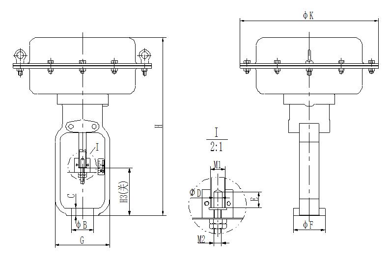
No handwheel mechanism
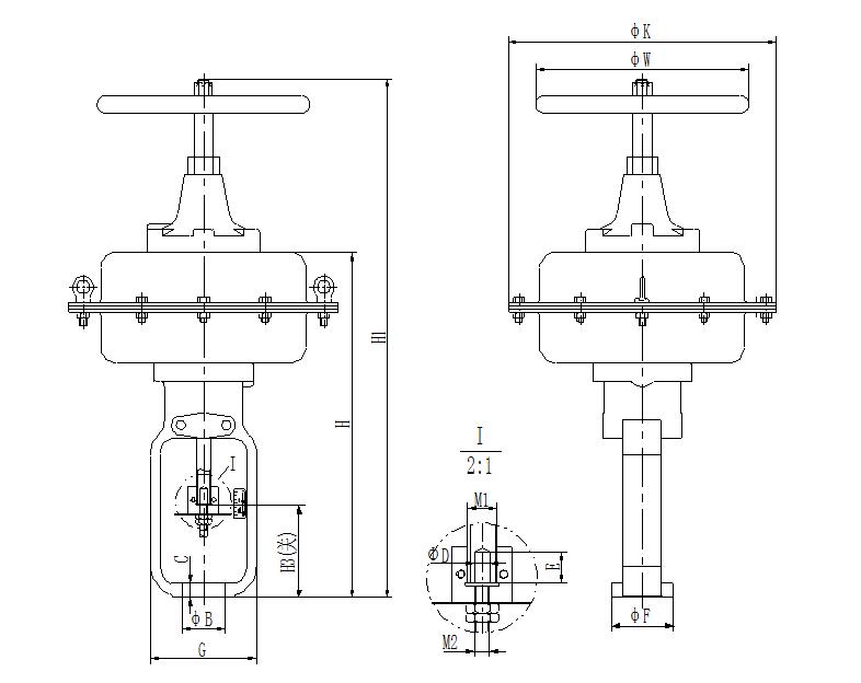
Top loading handwheel mechanism
Pneumatic film actuator (standard type)

Side-mounted handwheel mechanism
Size Unit:mm
Specification | 20 | 30 | 34 | 40 | 45 | 50 |
φB | 54 | 54 | 54 | 71 | 71 | 90 |
C | 19 | 19 | 19 | 24 | 24 | 35 |
φD | 10 | 10 | 10 | 13.5 | 13.5 | 20 |
E | 15 | 15 | 15 | 15 | 15 | 15 |
φF | 78 | 78 | 78 | 98 | 98 | 140 |
G | 134 | 134 | 134 | 162 | 162 | 216 |
H | 298 | 420 | 440 | 514 | 574 | 631 |
H1 | 458 | 579 | 660 | 734 | 862 | 919 |
H3(turn off) | 97 | 97 | 94 | 123 | 127 | 172 |
φK | 240 | 280 | 340 | 340 | 470 | 470 |
L | - | 280 | 280 | 290 | 310 | 315 |
L1 | - | 159 | 159 | 250 | 250 | 310 |
M1 | 5/8″-18UNF | 5/8″-18UNF | 3/4″-16UNF | 3/4″-16UNF | 1-1/8″-12UNF | 1-1/8″-12UNF |
M2 | 3/8″-24UNF | 3/8″-24UNF | 3/8″-24UNF | 1/2″-20UNF | 1/2″-20UNF | 3/4″-16UNF |
φW | 200 | 200 | 280 | 280 | 330 | 330 |
Itinerary | 19 | 19 | 29 | 38 | 51 | 51 |
Trachea connector | 1/4NPT | 1/4NPT | 1/4NPT | 1/4NPT | 1/4NPT | 1/4NPT |
Note: The maximum size of the air pipe joint of the actuator size 50 is 1/2NPT;
Pneumatic film actuator (standard type)

No handwheel mechanism
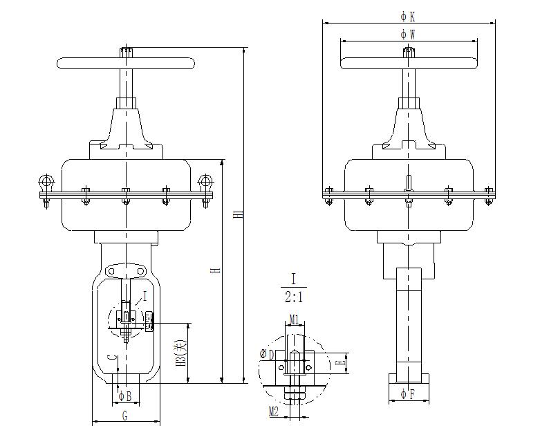
Top loading handwheel mechanism
Pneumatic film actuator (standard type)
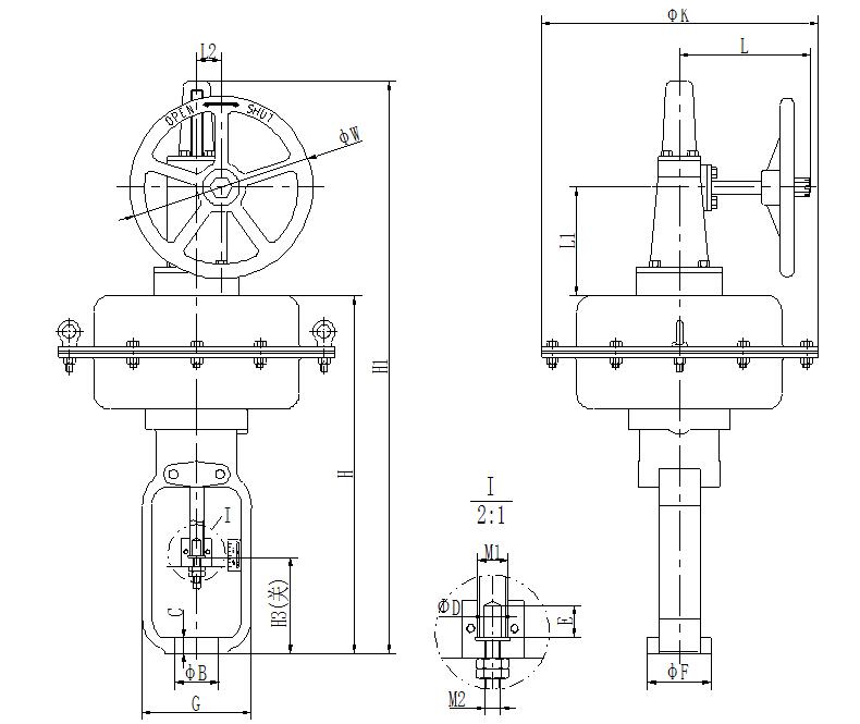
Side-mounted handwheel mechanism
Size Unit:mm
Specification | φB | C | φD | E | φF | G | H | H1 | H3 (Off) | φK | L | L1 | L2 | φW | 行程 |
70 | 90 | 35 | 20 | 15 | 140 | 216 | 804 | 1254 | 186 | 560 | 320 | 225 | 65 | 330 | 76 |
Note:
1. M1 thread size is 1-1/8"-12UN; M2 thread size is 3/4"-16UNF;
2. The size of the air supply piping interface is 1/2NPT.
Pneumatic film actuator (extended type)
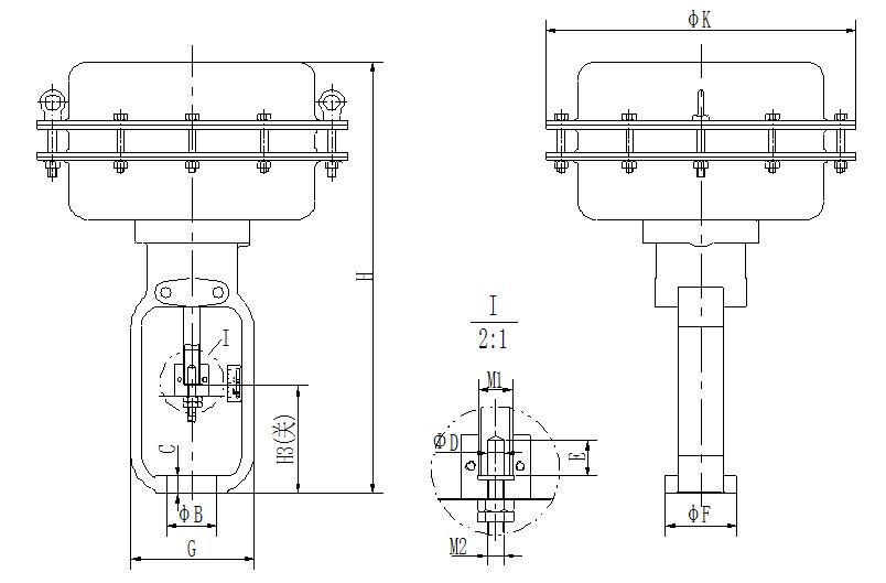
No handwheel mechanism
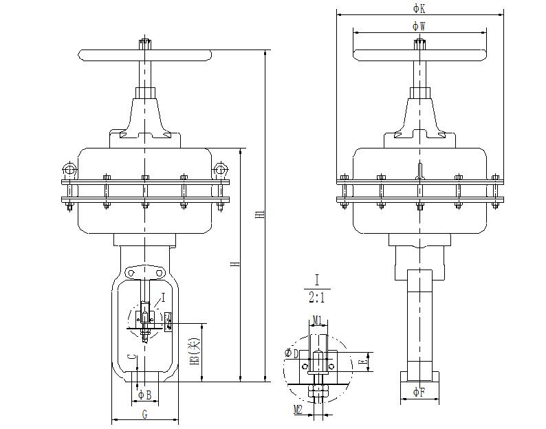
Top loading handwheel mechanism
Pneumatic film actuator (extended type)

Side-mounted handwheel mechanism
Size Unit:mm
Specification | 30 | 34 | 40 | 45 | 50 |
φB | 54 | 54 | 71 | 71 | 90 |
C | 19 | 19 | 24 | 24 | 35 |
φD | 10 | 10 | 13.5 | 13.5 | 20 |
E | 15 | 15 | 15 | 15 | 15 |
φF | 78 | 78 | 98 | 98 | 140 |
G | 134 | 134 | 162 | 162 | 216 |
H | 456 | 480 | 554 | 614 | 685 |
H1 | 615 | 700 | 774 | 902 | 973 |
H3(turn off) | 97 | 94 | 123 | 127 | 172 |
φK | 280 | 340 | 340 | 470 | 470 |
L | 280 | 280 | 290 | 310 | 315 |
L1 | 159 | 159 | 250 | 250 | 310 |
M1 | 5/8″-18UNF | 3/4″-16UNF | 3/4″-16UNF | 1-1/8″-12UNF | 1-1/8″-12UNF |
M2 | 3/8″-24UNF | 3/8″-24UNF | 1/2″-20UNF | 1/2″-20UNF | 3/4″-16UNF |
φW | 200 | 280 | 280 | 330 | 330 |
Itinerary | 29 | 38 | 51 | 76 | 76 |
Trachea connector | 1/4NPT | 1/4NPT | 1/4NPT | 1/4NPT | 1/4NPT |
Note: The maximum size of the air pipe joint of the actuator size 50 is 1/2NPT;
Pneumatic film actuator (extended type)
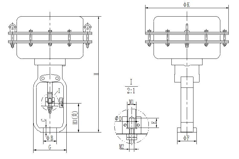
No handwheel mechanism

Top loading handwheel mechanism
Pneumatic film actuator (extended type)
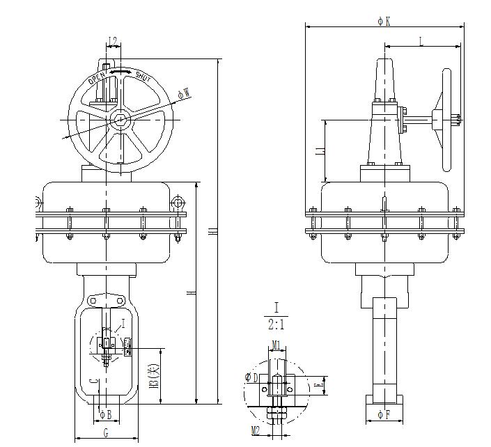
Side-mounted handwheel mechanism
Size Unit:mm
Specification | φB | C | φD | E | φF | G | H | H1 | H3(Off) | φK | L | L1 | L2 | φW | Stroke |
70 | 90 | 35 | 20 | 15 | 140 | 216 | 875 | 1325 | 186 | 560 | 320 | 225 | 65 | 330 | 102 |
Note:
1. M1 thread size is 1-1/8"-12UN; M2 thread size is 3/4"-16UNF;
2. The size of the air supply piping interface is 1/2NPT.